Pegasus Hobbies Future War Aerial HK Machine
A modification for the Pegasus Hobbies Future War Aerial HK Machine. The model is a 1/32 scale model kit available from a number of locations. Modified with LEDs in the tail, landing lights, search lights and plasma gun. Added servos to control the VTOL jets and a modified base (built with Lego) to control turn and tilt of the model.
Parts
First some parts. None of the makes suggested here are endorsements. You should do your own research and buy what you feel is best.
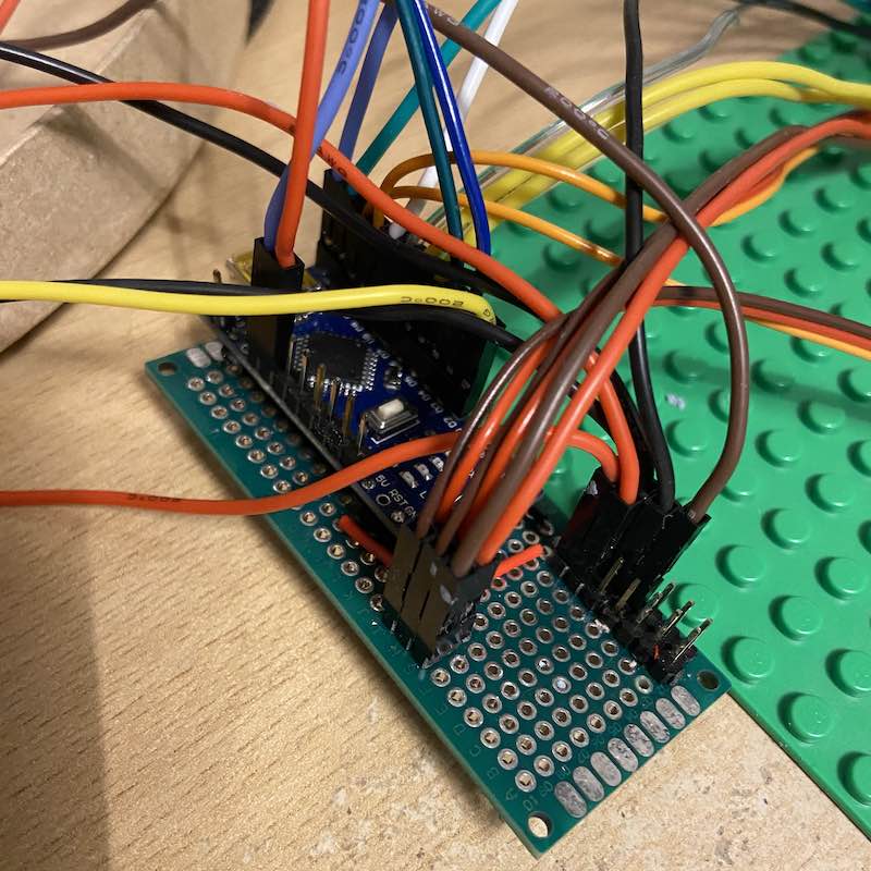
- An Arduino Nano. I used one from Ebay but also ran some tests using an official one from somewhere like The PI Hut which is much more expensive (but has pins soldered).
- Three KY66 micro-servos (two for the thrusters and one to control the tilt). I bought a pack of 10 from Longrunner on Amazon.
- One MG90S to control the turn. One with metal gears as it takes the weight of the model. There are lots of poor quality MG90S fakes around, so don’t go for a cheap one. I used these from Amazon.
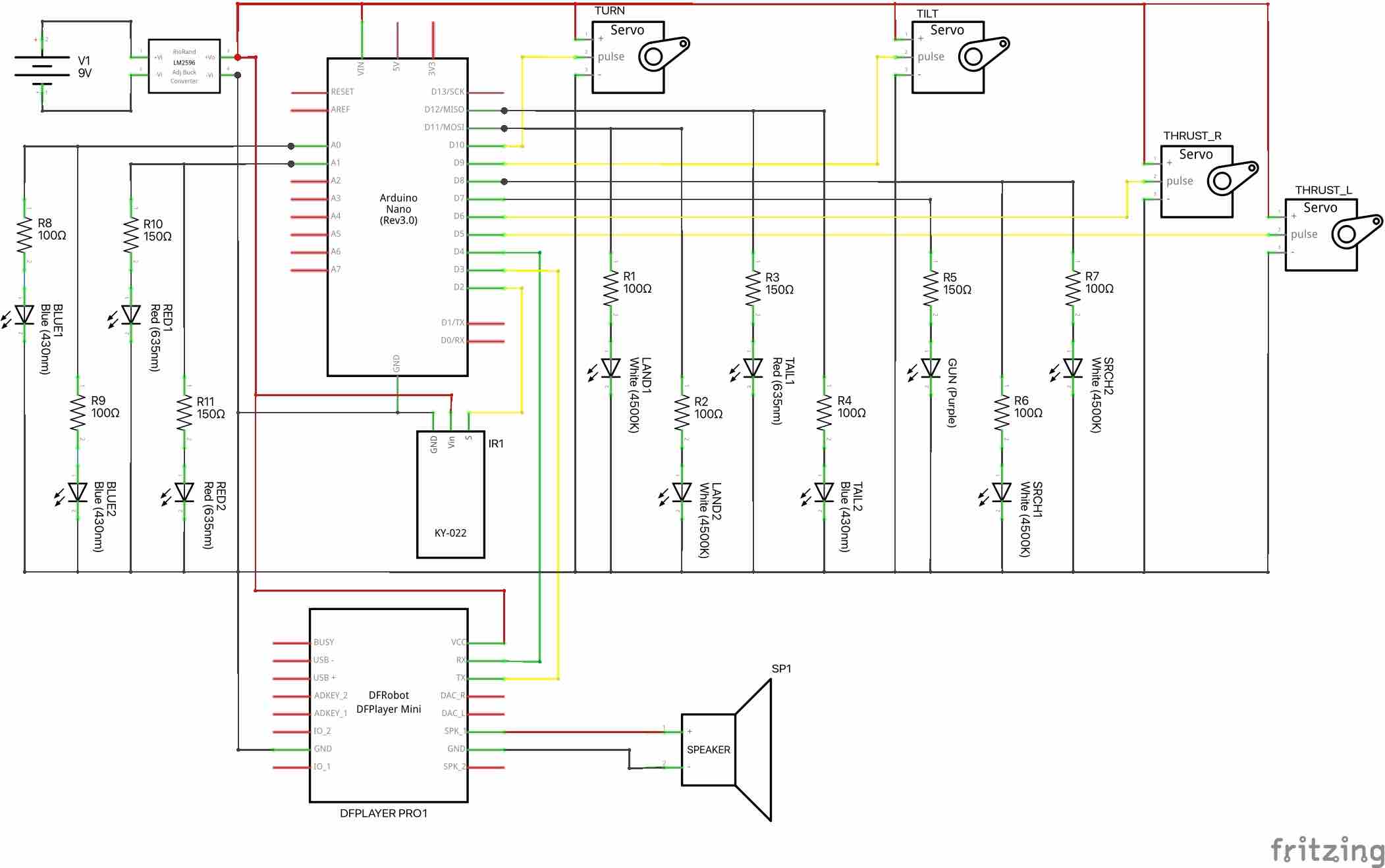
- DFPlayer Pro MP3 Card. I used this one from The PI Hut. On the schematic below, it says DF Player Mini, because I could not find the DFPlayer Pro schematic.
- An LM2596 DC-to-DC Buck Convertor such as this example to step down a power adapter voltage to 5V DC and to provide enough current to drive the Arduino, servos, bright LEDs and periferal devices.
- Associated 5A DC Power Connector like this example.
- An 8W 3-ohm speaker. For example this one from ebay.
- IR Receiver Module and controller.
- Mini multicolor LEDs for the tail. These need to be very small (model railway lamps and lights size) to fit into the tail wing cavity.
- Super-bright white LEDs for landing and search lights like this example.
- Purple LED like these from EBay for the plasma gun.
- Some resistors to protect each LED from full voltage. The Arduino puts 5v to each IO pin which is too much for LEDs which require about 1.8-2.1v. I used 100 and 150 ohm (see the schematic).
- Some AWG 24 wiring to connect things together. Either multi-core or solid core. These options provide much more than required, depending on your needs. I used solid core (stays as bent) within the HK and flexible core in the drop down to the base.
- Heat shrink tubing such as this I used from Amazon.
- A PCB Prototype board such as this example
- Mail and female Dupont connectors.
You will also need a soldering iron and some solder to connect things together. A crimping tool to create the connector cables. Hot glue and glue sticks. I used this one from Hobby Craft.
Circuit Schematic
Assembly
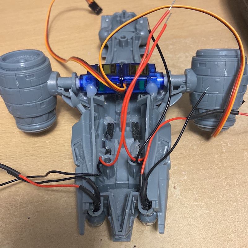
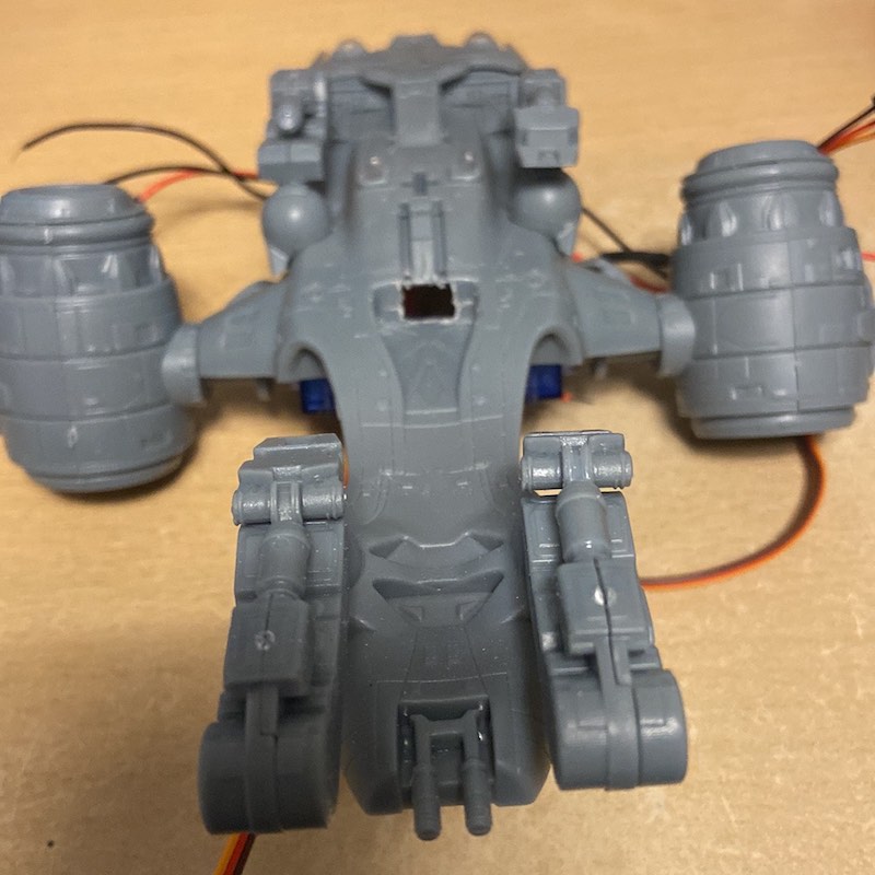
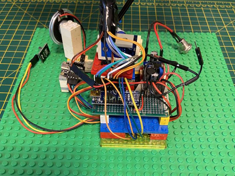
This is how I fitted the internals to the main body. See the pictures below for visuals.
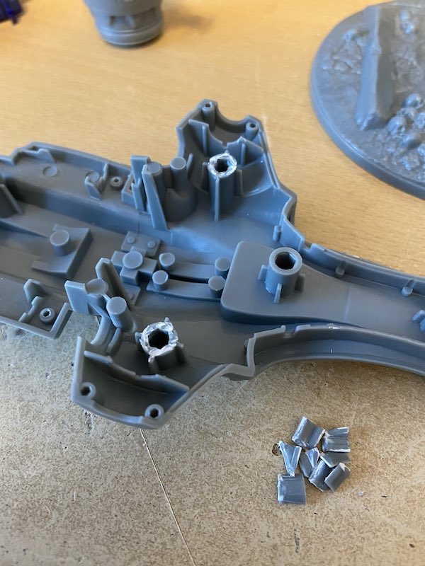
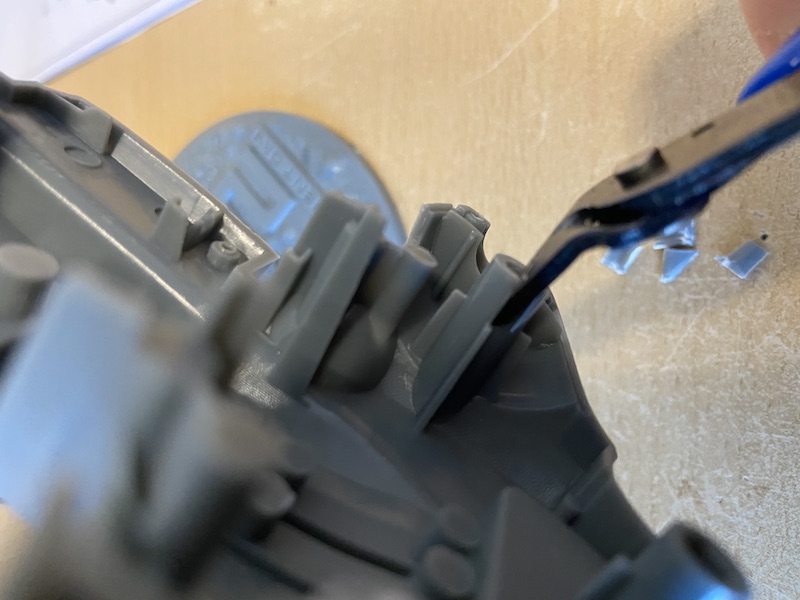
- Before fitting the servos, some cutting of struts in the main body is required to make room.
- Slowly cut the struts down and check if the servo sits in line with the thrusters.
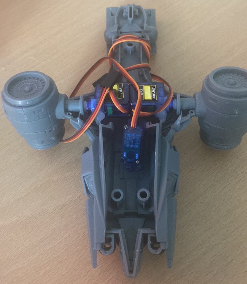
- Once aligned, glue the two KY66 servos back-to-back to control the thrusters, glued in place in the model body.
- Then fit the search and landing lights.
- Cut a hole in the bottom of the model to feed wires through to the base.
- I layed wires to the tail lights (using just LEDs to prove wiring prior to using the miniature LEDs into the tail wings later)
At this point I painted the model chrome, but you may prefer to paint at the end as there’s some handling of the model.
Lay the tail lights into the tail wings so they shine through the clear tail light ends. I recommend connecting up and testing everything works before glueing everything together (I speak from experience).
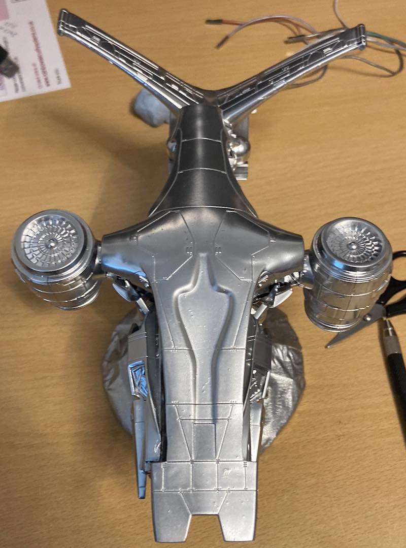
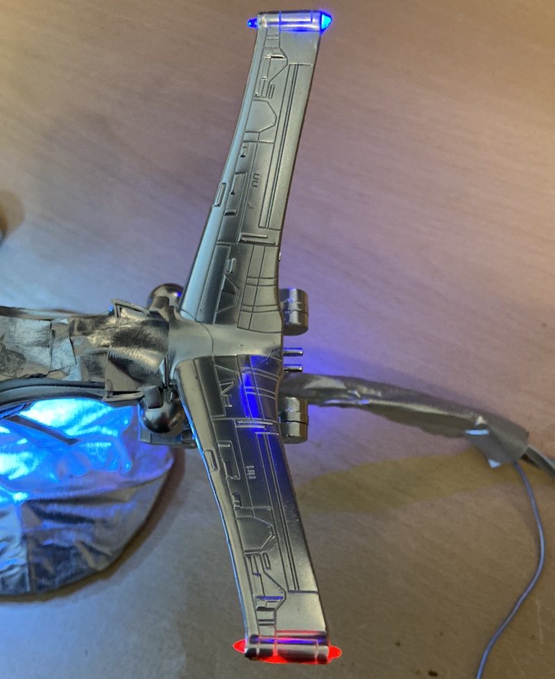
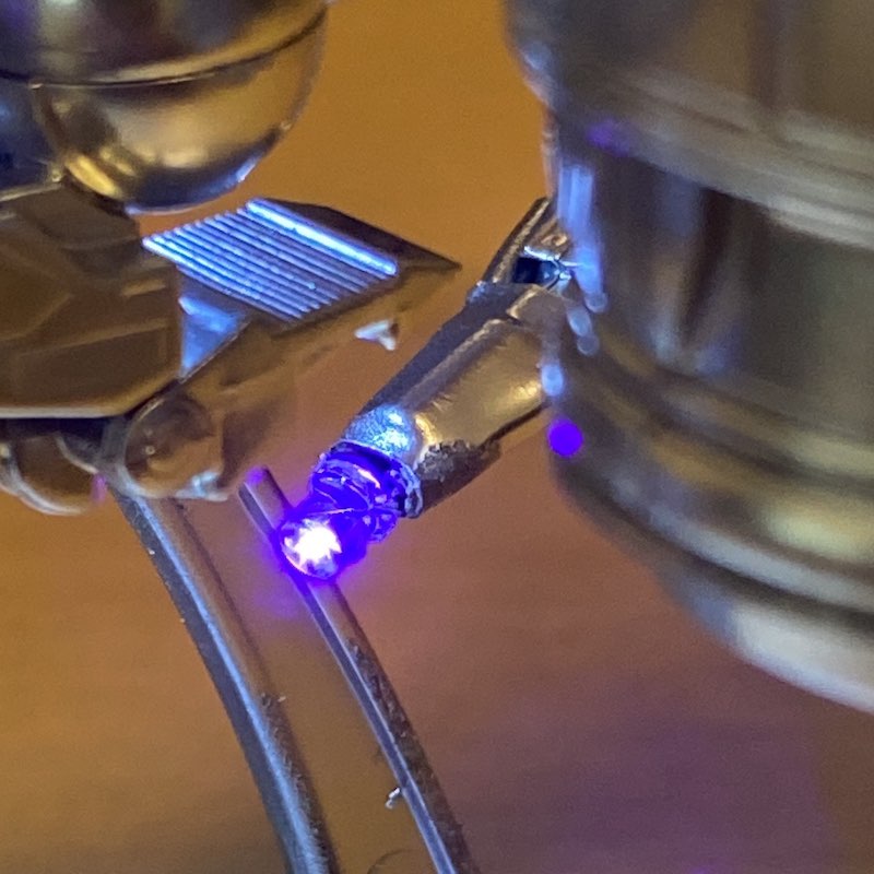
For the plasma gun, fix the purple LED with it’s anode & cathode down the length of the gun and use heat shrink tubing to secure in place. It doesn’t show once spray-painted silver.
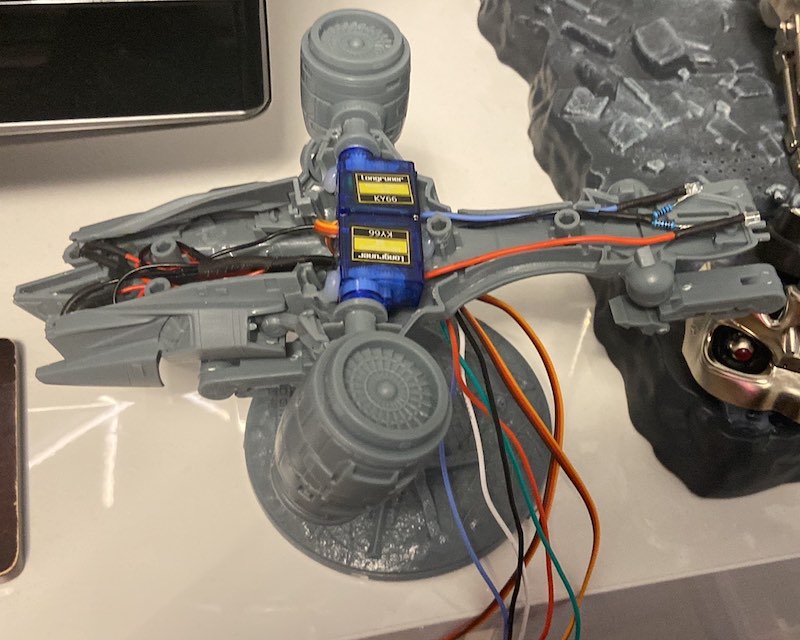
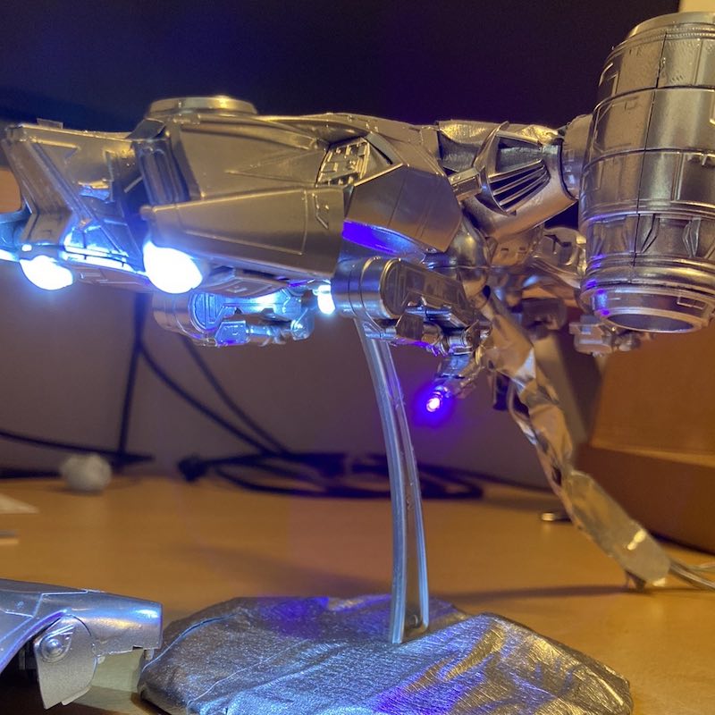
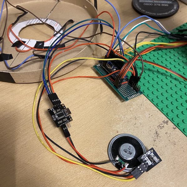
From the last two pictures, you can see how the cabling comes down from the model into the base electronics and how the peripherals are linked to the base electronics also. There are more pictures of the cabling later.
Mounting
Once you have everything connected up, it’s time to mount the model on a stand. I used Lego because you can build it to fit yor needs (and I had some old lego left over from my childhood). Other options might be suitable. With Lego I had to modify some parts so they held the turn servo securely in place (a ladder with the rungs filed flat).
My first version didn’t have the rotate servo underneath and used arms to turn the main shaft. See the design on BrickLink. There was some wobble when turning the model back and forth.
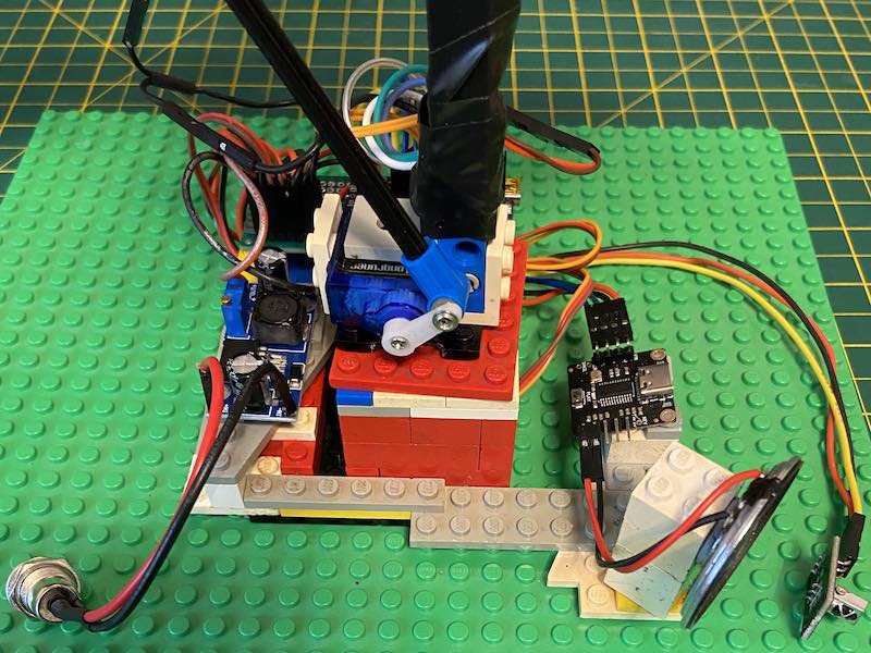
After some experimentation, I built a base around the MG90S turn servo with flat tiles on top. The servo horn was glued to a plate with a hole (with some filing of the underside). The hole so the screw can hold the horn onto the servo. I then layed the tilt servo flat (to minimise height) using some 90 degree brackets and a Technical Lego strut up to the model (bound with black tape in the pictures).
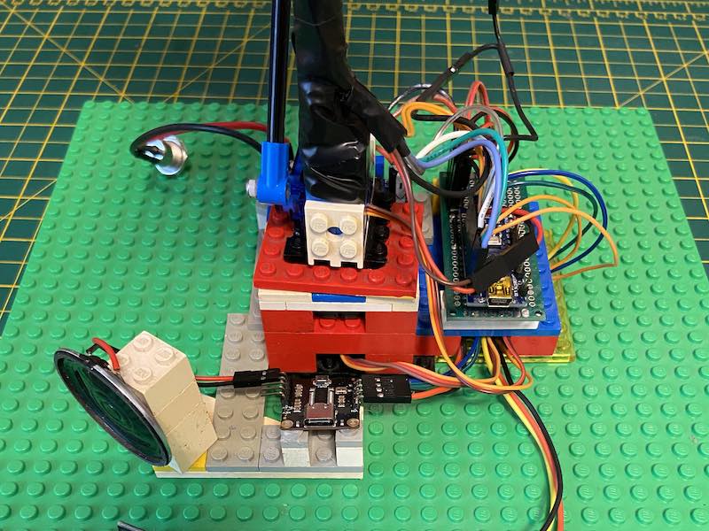
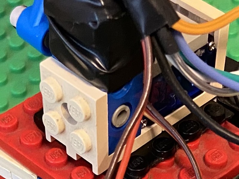
You can see the two (white) right angle brackets facing away from each other and the other grey right angle bracket attached to the strut (partially covered with the black tape in the picture).
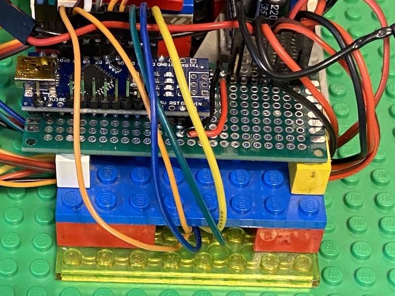
This Lego all fits in the base unit of my model and is hot-glued down to keep it still. The remote control sensor protrudes at the front and the power socket out the back. You would need to build your base mount to fit your base unit.
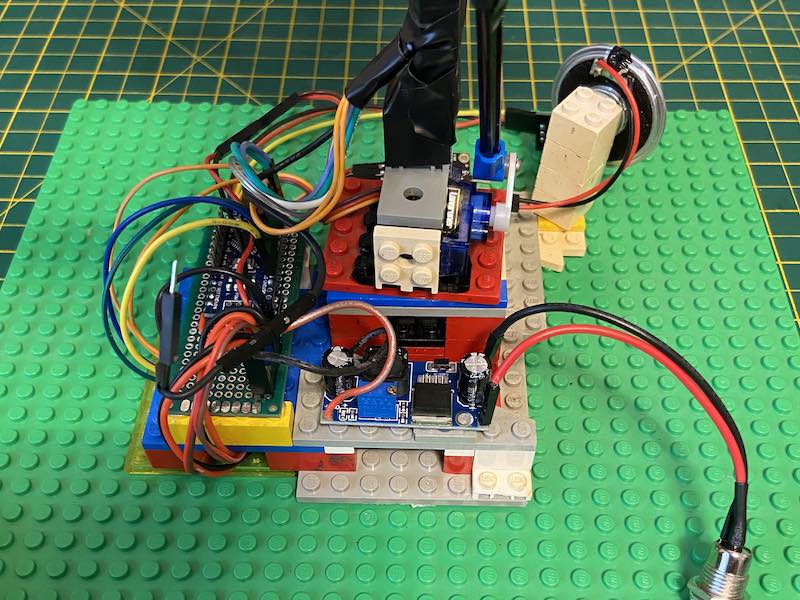
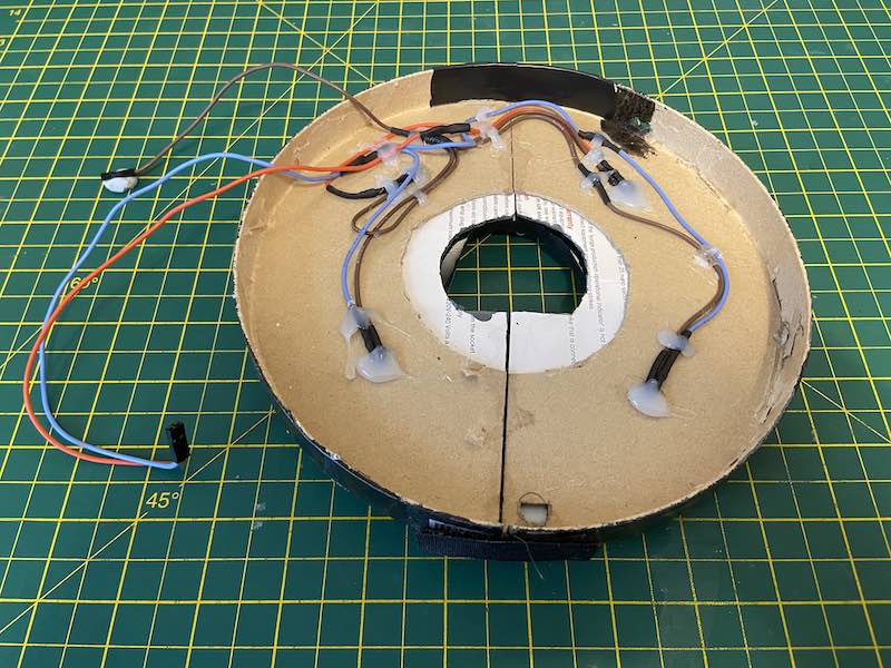
To stop the cables interfering with the turn motion, I hot-glued the circuit boards onto a platform with space underneath to route power and signal cables underneath. The one unconnected black ground wire is for the red and blue lights on the top of the base unit.
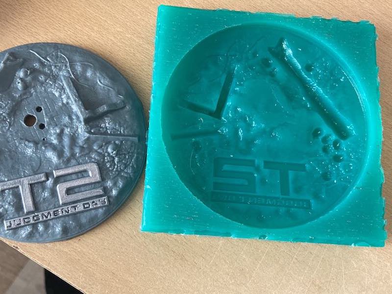
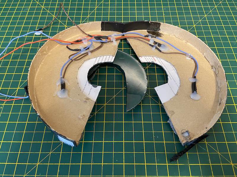
To make the top of the base unit, I duplicated the original base using mold making silicone and resin. Once cured, I cut it so it fits round the stand and tilt struts upto the model. I laid the red and blue base unit lights, hot-glued on the underside with the cables crossing at the back of the underside (near a hinge made from black tape).
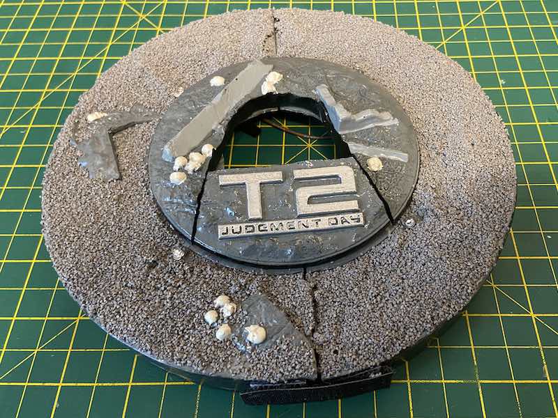
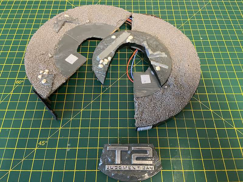

Putting everything together hides the base mount in the base unit. With some painting, decals and model railway gravel, the Terminator Aerial Hunter-Killer enhancements are complete.